Table of Contents
Mains supply connector is described as AC 230V
and is in the middle of the lower edge of the regulator's main plate.
The regulator IS NOT equipped with its own power supply switch,
what means that an external mechanism must be provided
for mains power supply shutdown.
Connection contacts are described as N and L,
what means Neutral (zero wire, blue color) and Live (phase wire, brown color).
Maintaining appropriate sequence of connecting wires N and L is not vital for
correct operation of the machine, however, it is highly recommended owing to preservation of the convention
and elegance of the installation.
Connector of earth is described as EARTH and is located on the left side
of the mains supply connector.
Earthing should be running in a separate, dedicated cable in color green-yellow (in accordance with appropriate standards), with eye tip phi 4mm, screwed down in the regulator to the screw clamp EARTH and connected outside to the respective earth.
![[Caution]](images/caution.png) |
Caution |
|---|---|
|
To ensure safety of use, proper operation of the regulator and immunity to interference, it is necessary to ensure appropriate connection of the earth clamp! IT IS NOT allowed to connect the earth clamp to contact N of the power supply connector ! Separate earthing is required. |
LB-762 regulator is equipped with a number of inputs, ensuring attachment of the following probes:
2 psychrometers,
4 temperature probes of air-conditioning tunnel,
6 base temperature probes,
1 extra universal temperature probe.
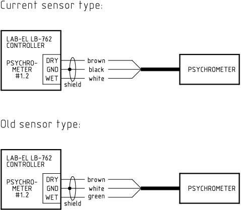
LB-762 regulator may cooperate directly with two psychrometers. When connected only to one psychrometer, it is used for measurement of temperature and humidity in the cultivation hall. The second psychrometer may be used also for measurement of temperature and humidity in the hall - in such case the regulator averages results from both measuring points, providing greater independence of measurement from the gradient of temperatures and humidity in the cultivation hall. The second psychrometer may also be used for other purposes, such as e.g. measurement of air parameters on the outlet of air-conditioning tunnel. The basic psychrometer should be connected to input #1.
Psychrometer connectors are marked as:
PSYCHROMETER #1,
PSYCHROMETER #2.
Each of the psychrometers is attached using three wires:
DRY - dry thermometer,
GND - common wire (ground),
WET - wet thermometer.
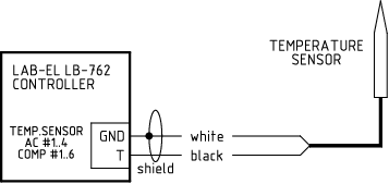
For connecting temperature probes the following connectors are used:
TEMP.SENSOR AC #1 - the thermometer of air-conditioning tunnel no. 1 (behind the heater),
TEMP.SENSOR AC #2 - the thermometer of air-conditioning tunnel no. 2 (behind the cooler),
TEMP.SENSOR AC #3 - the thermometer of air-conditioning tunnel no. 3 (additional),
TEMP.SENSOR AC #4 - the thermometer of air-conditioning tunnel no. 4 (additional),
TEMP.SENSOR COMP #1 - base thermometer no. 1,
TEMP.SENSOR COMP #2 - base thermometer no. 2,
TEMP.SENSOR COMP #3 - base thermometer no. 3,
TEMP.SENSOR COMP #4 - base thermometer no. 4,
TEMP.SENSOR COMP #5 - base thermometer no. 5,
TEMP.SENSOR COMP #6 - base thermometer no. 6,
TEMP.SENSOR AUX #1 - additional thermometer.
Each of temperature probes is attached using two wires:
T - temperature sensor,
GND - ground.
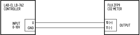
Analog input 0-10V is described as INPUT 0-10V.
To this input one can attach any source of signal within the measuring range 0-10V,
e.g. CO concentration meter 2.
The connection is done using two wires:
U - signal input,
GND - ground.
Figure 3.3, “Scheme of connection of FUJI ZFP9 type meter” presents a scheme of connection of CO concentration meter 2 type FUJI ZFP9. Another type of meters are connected in the same manner. After meter connection to the analog input 0-10V one should adequately configure the regulator so that it could read data from the meter. One should indicate the place of connection of the meter and the type of meter – additionally, individual calibration can be made of the particular meter.
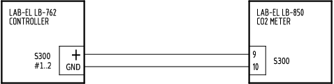
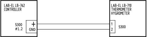
LB-762 regulator is equipped with two inputs permitting attachment of any S300 sensors, extending measurement possibilities of the regulator. In typical cases these are concentration meters CO2 LB-850 or hytherographs LB-710.
For connecting sensors the following connectors are used:
S300 #1 - sensor input no. 1,
S300 #2 - sensor input no. 2.
The connection is done using two wires that they provide power supply to the meter and are used for data transmission:
”+” - power supply,
GND - ground.
S300 interface is a current loop which permits any polarization of the attached sensor, thus the manner of connection (sequence of wires) does not have any importance here.
Figure 3.4, “Scheme of connection of LAB-EL LB-850 type meter” presents a scheme of connection of concentration meter CO2 type LAB-EL LB-850. The meter can be attached to any of the two S300 inputs which LB-762 regulator is equipped with. After connection of the meter to S300 input it is necessary to properly configure the regulator, so as to ensure that it could use measurement data from the S300 input.
Figure 3.5, “Scheme of connection of LAB-EL LB-710 type meter” presents a scheme of connection of hyterograph type LAB-EL LB-710. The meter can be attached to any of the two S300 inputs which LB-762 regulator is equipped with. After connection of the meter to S300 input it is necessary to properly configure the regulator, so as to ensure that it could use measurement data from the S300 input.
LB-762 regulator is equipped with 8 relay outputs, used to control any executive devices. For connecting executive devices, the following connectors are used:
RELAY #1 - relay no. 1 (contact),
RELAY #2 - relay no. 2 (contact),
RELAY #3 - relay no. 3 (contact),
RELAY #4 - relay no. 4 (contact),
RELAY #5 - relay no. 5 (contact),
RELAY #6 - relay no. 6 (contact),
RELAY #7 - relay no. 7 (contact),
RELAY #8 - relay no. 8 (contact - no contact).
Relays 1-7 are shorted, contacts are marked as N.O.
(what means inactive condition ”Normally Open” – normally no contact).
Switching on the relay causes short circuit of output contacts.
Relay no. 8 is of contact-no contact type, pairs of contacts are marked as
N.O. (what means inactive condition ”Normally Open” – normally no contact)
and
N.C. (what means inactive condition ”Normally Closed” – normally contact).
One contact is common.
Switching on the relay causes short circuit of output contacts N.O.
and opening of contacts N.C.
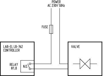
Relay outputs are completely insulated galvanically from all other connectors, in particular from the mains supply. This means that these relays can control any circuits, independently of existing voltages. In any case external power supply is required to the executive device – the regulator does not emit voltage on relay outputs.
Figure 3.6, “Scheme of connection system of a typical valve to relay output” presents a scheme of connection of a typical valve to the relay output. External connection is required of power supply voltage (the regulator does not emit power supply on relay outputs), additionally, it is necessary to use an appropriate fuse protecting the circuit against short-circuit.
LB-762 regulator is equipped with 8 connectors used for connection of analog servomotors. The outputs permit control of any servomotors which accept control signal within the range 0-10V or 2-10V. Apart from control of servomotor it is also possible to connect return signal from servomotor, informing about the current position of the servomotor. Scope of voltages of return signal is analogous to the control output: 0-10 or 2-10V. The return signal is used by the regulator to control correct operation of the servomotor (check whether the servomotor is set in accordance with the preset control signal). If the servomotor has no return signal output or is not used in the given installation, one should make the connection according to Figure 3.9, “Scheme of connection of analog servomotor without return signal”.
Connectors of regulator LB-762 intended for cooperation with servomotors are marked as follows:
ACTUATOR #1 - servomotor no. 1,
ACTUATOR #2 - servomotor no. 2,
ACTUATOR #3 - servomotor no. 3,
ACTUATOR #4 - servomotor no. 4,
ACTUATOR #5 - servomotor no. 5,
ACTUATOR #6 - servomotor no. 6,
ACTUATOR #7 - servomotor no. 7,
ACTUATOR #8 - servomotor no. 8.
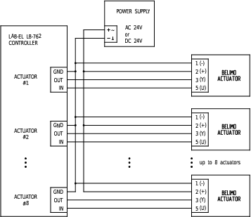
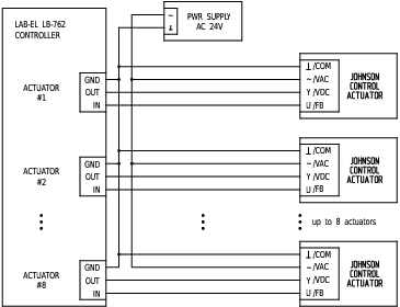
LB-762 regulator does not supply power to servomotors – servomotors require a separate source of power supply. The manner of power supply depends on the type of servomotors. Popular BELIMO servomotors can be powered with voltage 24V AC or 24V DC, Johnson Control servomotors require only 24V AC power supply.
For 24V AC power supply the so-called safety transformer can be used 230V/24V, one should however ensure proper anti-shorting protection.
The power supply unit can be one common for all servomotors – it must however ensure appropriate current efficiency (one should calculate the sum of input power by all servomotors and depending on this power accordingly select efficient power supply). Configuration is also possible in which each servomotor has its own individual power supply.
If both analog and digital servomotors are used in the system, their common power supply is possible – see description of digital servomotor power supply, found below in the manual.
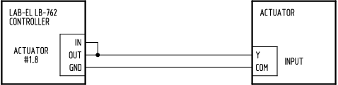
3 contacts are provided for connection of each servomotor:
IN - return signal input informing about position of the servomotor,
OUT - control signal output fixing servomotor position,
GND - ground.
GND contact is present on each of the connectors, but this is a common signal without galvanic insulation between different connectors, what can be use to possibly simplify cabling.
Figure 3.7, “Scheme of connection of analog servomotors Belimo” and Figure 3.8, “Scheme of connection of analog servomotors Johnson Control” present typical connection diagrams for Belimo and Johnson Control servomotors.
For servomotor which does not have a return signal, one should short-circuit contacts IN and OUT in the given connector of regulator LB-762 in accordance with figure Figure 3.9, “Scheme of connection of analog servomotor without return signal”. Such connection will ensure ”cheating” of the regulator as to compliance of the set and the actual servomotor position and shall prevent alert signalling of servomotor failure.
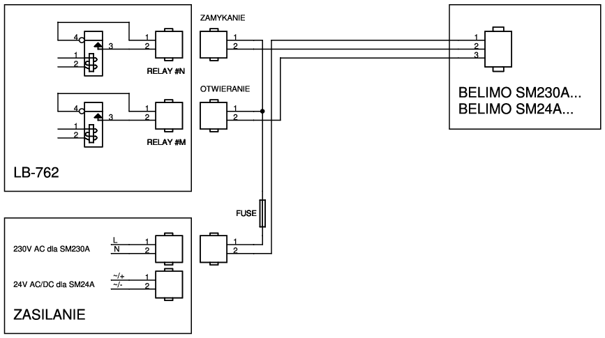
For open-close actuator control, 2 separate relay outputs are used. First relay controls ”open” action, the second one controls ”close” action. Both relays must be properly configured in controller.
Using the same method, one can control engine, instead of actuator. Additional external circuitry is required, to properly switch engine rotation direction.
LB-762 regulator is equipped with one connector used for connection of a bus of digital servomotors consistent with BELIMO MP-BUS standard. By means of this bus the regulator permits operation of 1 servomotor configured in PP mode or from 1 to 8 servomotors in MP mode. The key advantage of MP-BUS bus as compared with analog controlled servomotors is important simplification and reduction in the quantity of cabling (instead of 3 separate ducts from each servomotor to the regulator only 3 wires are conducted in parallel to each servomotor), better diagnostics (the regulator is able to detect lack of correct communication with the servomotor – e.g. in consequence of damage of servomotor, power supply unit or cabling) and more precise servomotor positioning and reading of its actual position (digital data transmission resistant to interference).
For cooperation with MP-BUS bus suitable servomotors must be used, consistent with this standard. Before connection to the system they require configuration – address setting. Default, factory servomotor setting permits operation in PP mode (permitting communication only with one servomotor), use of a greater number of servomotor requires assignment of an individual address to each one. Servomotor address setup procedure is described further in the manual.
MP-BUS bus is galvanically insulated from all other connectors of LB-762 regulator, in order to ensure greater immunity to interference created by digital data transmission.
LB-762 regulator does not supply power to servomotors – servomotors require a separate, own source of power supply 24V DC or 24V AC (BELIMO servomotors can be powered by both direct and alternate current). In the case of AC power supply polarization of power supply does not have any importance here, for DC power supply attention should be paid to correct polarization (see scheme of connections).
The power supply unit can be one common for all servomotors – it must however ensure appropriate current efficiency (for example for digital servomotor LM24A-MP maximum power consumption is 3W, what means 24W with 8 servomotors peak power consumption; depending on the number and type of servomotors used appropriate power supply efficiency should be considered).
For a system using both analog and digital servomotors, it is also possible to provide their common power supply from one power supply unit - in such case one should connect contact GND of connector BELIMO PP/MP with contacts GND of joints of analog servomotors (ACTUATOR #N), as there is no connection between these contacts inside the regulator (galvanic insulation).
24V DC power supply to servomotors has the advantage of permitting longer connecting cables than 24V AC power supply – see the description below. However, it must be quite well filtered out – the amplitude of pulsations cannot be higher than 10 %.
MP-BUS bus imposes some restrictions as to the length of cabling and section of wires. While the type of cable has no greater importance (it does not have to be screened, simplest 3-conductor cable is sufficient), , depending on the type of power supply (AC/DC), the number of servomotors and the section of the connection cable, different is the maximum acceptable cable length. Detailed information on the method of setting the maximum connection cable length can be found in the documentation of Belimo, below presented are the most typical cases for cable with core section 0.75 mm2 and popular types of servomotors.
Table 3.1. Maximum cable length for section 0.75 mm mm2
| consumed power | power supply 24V AC | power supply 24V DC |
|---|---|---|
| 20 W/VA | 25 m | 40 m |
| 40 W/VA | 15 m | 20 m |
| 60 W/VA | 8 m | 10 m |
One should sum up power collected for all connected servomotors. For example for servomotor LM24A-MP consumed power is 2.5 W for 24V DC and 5.0 VA for 24V AC. With 8 servomotors we have the sum of powers 20 W for 24V DC and 40 VA for 24V AC, what permits application of cable with length respectively 40 meters at supply 24V DC and 15 meters at supply 24V AC.
In special cases when larger distances are required, double increase in the cable section up to 1.5 mm2 permits twofold growth in these distances.
In the case when each servomotor has its own power supply located in the neighborhood of the servomotor, connection of MP-BUS bus with LB-762 regulator can be made by two cables. In such case cable length is restricted to 800 meters, regardless of its section (it is not however recommended to use cable with section smaller than 0.75 mm2).
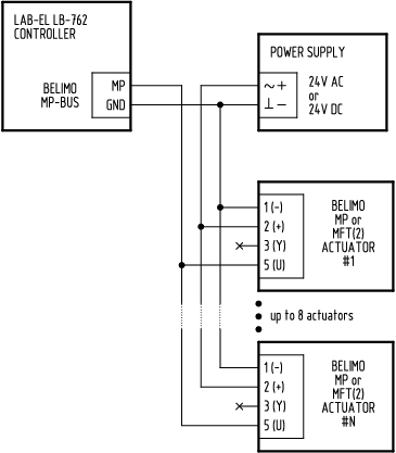
Connector of LB-762 regulator used for connection of MP-BUS bus is described
as BELIMO PP/MP and is equipped with 2 contacts:
MP - signal,
GND - ground.
Figure 3.11, “Scheme of connection of bus of servomotors BELIMO MP-BUS” presents the typical manner of connection of MP-BUS bus, using additional common 24V power supply unit.
The manner of laying the cable between LB-762 regulator, the power supply unit and servomotors has no importance here. It can be running in any convenient way, this may be a layout of bus, star, mixed or any other.
More details concerning MP-BUS bus and its technical parameters can be found in BELIMO documentation.
Factory standard setting of BELIMO servomotor is operation in PP mode, which allows connection of only one servomotor to MP-BUS bus. Operation in MP mode allows connection of 1 to 8 servomotors, but requires setting of individual addresses for the servomotors, so as to ensure that the regulator could communicate with each servomotor independently of the others. In PP mode one can also connect a servomotor with set MP address, however, the address is then used and the servomotor operates always independently of the set address.
For proper cooperation of LB-762 regulator with digital servomotors BELIMO MP-BUS one should correctly configure both the servomotors and the regulator itself, according to the used operation mode of the servomotors (PP or MP with addresses).
The configuration of servomotor addresses can be done in several ways:
ordering appropriate configuration settings from the producer – not quite practical method, as the configuration has to be fixed at the order,
BELIMO configuration tools – such as MFT-H programmer or interfaces ZIP-RS232, ZIP-USB-MP, ZIP-232-MP, ZIP-232-KA plus dedicated Belimo PC-Tool MFT-P configuration software; description the method of conduct is in the respective documentation of Belimo,
configuration procedure built in LB-762 regulator – this method is described below.
LB-762 regulator software permitting configuration of addresses of attached servomotors. Individual connection of each servomotor is not required - the configuration can be made after completing full installation with all servomotors. The servomotors must have power supply on and must be respectively connected to the regulator.
![[Important]](images/important.png) |
Important |
|---|---|
The necessary condition for correct operation of servomotors is to assign individual addresses to them. Each MP-BUS servomotor attached to the particular regulator must have a unique address! |
The procedure below applies to one servomotor, it should be repeated for each installed servomotor:
enable programming of the regulator (PROGRAMMING button on remote control, specify the respective regulator number),
go to advanced settings menu (button PASSWORD, enter correct password – this is normally 1111),
choose MP-BUS servomotor addressing function (button B),
at any moment use button BACK to cancel the procedure of servomotor address setup,
in response to message MP-BUS addr = enter the required
servomotor address (1 to 8),
the regulator will display the blinking hint SET ACT,
in response to which the address setting should be confirmed
in the desired servomotor – the procedure depends on the type of servomotor.
Possible are the following options (more information can be found in the Belimo documentation):
servomotors...-MP: after switching on the address setup procedure on servomotor the yellow indicator should regularly flash; to confirm the address press this control (it is at the same time a button) and hold until the address is confirmed (control off and address confirmation on the regulator),
servomotors LM,NM,AM,GM...-MFT(2): push disengagement button only once, hold it pressed until the address is confirmed on the regulator,
servomotors LF,AF...-MFT(2): over less than 5 seconds change twice the position of sense of rotation switch (L/R),
servomotors NV,NVF,AV...-MFT(2): after switching on the address setup procedure on servomotor indicator H1 should flash (alternately red and green); to confirm the address press S2 button only once, hold it pressed until the address is confirmed on the regulator.
after confirming the address the regulator should display message
SET ACT without flashing, what means confirmation of correct
address setting. If the regulator displays message Err,
this means an error in communication with the servomotor – try
to repeat the operation. If the error persists, this means a problem
in communication with the servomotor – check the connections as
well as the possibility of address collision with other servomotors. In such
situations immediate disconnection can help of the other servomotors
and conduct of the address setting procedure with a single
servomotor connected. Continuous flashing of announcement SET ACT
and no reaction to confirm the address in servomotor
means no communication with the servomotor – check
the correctness of all connections,
after setting the servomotor address, use button NEXT to go to address setup for the next servomotor, or use BACK button to end the address setup procedure.
LB-762 regulator is equipped with two analog outputs 0-10V, marked as follows:
OUTPUT 0-10V #1 - output no 1,
OUTPUT 0-10V #2 - output no 2.
For connection of device 2 contacts are provided:
U - voltage signal 0-10V,
GND - ground.
Both outputs are insulated galvanically from all other signals, as well as from each other. They are designed for cooperation with devices generating an elevated level of interference as e.g. inverters controlling engine rotations. Of course it is possible to use these outputs for any other purposes – they are universal and can be used for connection of any device that is subject to control by signal 0-10V (or 2-10V).
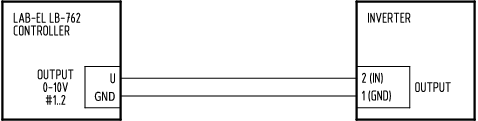
Figure 3.12. Scheme of connection of frequency converter type OBRUSN PC3.., OBRUSN PC4.., SSD Drives 605, SSD Drives 650 and similar
RJ45 type connector is used for connection with other network devices by means of cable-spiral, according to standard 10BASE-T and 100BASE-T. In order to obtain as high immunity to interference as possible, for connection use high quality cable Cat 5 or Cat 5e. The maximum acceptable length of a single connection is 100m (from one device to the other, namely e.g. from regulator to switch).
When using Ethernet network for controllers and PC connection, it's necessary to properly configure IP addresses. Below is a sample configuration, assuming usage of private IP address range. It's typical configuration for standalone system, when there's no need for routing between regulators and control software via other networks. Figure 1.3, “Scheme of a system with several LB-762 regulators and Ethernet network” presents connection diagram for such simple system. 192.168.100.0 network address will be used, preventing conflicts with most popular 192.168.1.0 network, if one is already in use. Static addresses will be assigned to network nodes - autoconfiguration with BOOTP/DHCP protocols is not used.
regulators #1..99: addresses 192.168.100.1 .. 192.168.100.99
komputer PC: 192.168.100.100
optionally additional router (ex. to Internet): 192.168.100.254
Subnet mask: for all network nodes it's the same: 255.255.255.0
Default gateway: if router is present in the network, its address should be used (192.168.100.254), otherwise gateway address doesn't matter - regulators can be set with 0.0.0.0 address, or PC address (192.168.100.100).
Proper settings (IP address, subnet mask, gateway) should be set for every network node (regulators, PC, router) - but every device gets it's own unique IP address. Subnet mask and gateway address are the same for all nodes.
Regulator address settings can be applied using lbnetcfg tool, PC with Windows operating system requires changes to network card settings, under TCP/IP protocol properties.
The connector described as RS-485 is used to connect LB-762 regulator
to RS-485 network, serving for communication with an appropriate
IT system (PC computer and appropriate software).
For connection of RS-485 network 3 contacts are provided:
A - signal,
B - signal,
GND - ground.
RS-485 bus is galvanically insulated from all other signals.
In order to obtain as high immunity to interference as possible, for RS-485 network connection use two-pair screened spiral, with minimal wire section 0.2 mm2. One pair of wires should be connected to contacts A and B, the second pair together with the screen connected to contact GND.
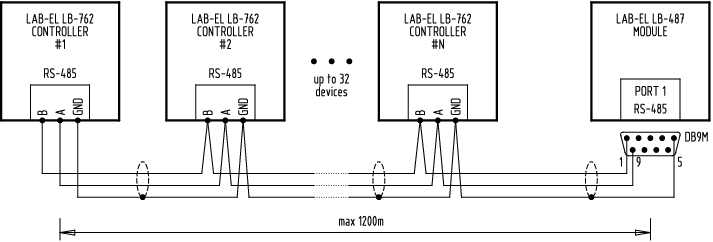
Total length of RS-485 network may be max. 1200 meters.
Figure 3.13, “Scheme of RS-485 network connection” presents the manner of RS-485 network connection. The Connecting cable must be laid from one device to the next one, branching must be directly on connecting clamps – on the diagram points marked with dots.
Numbers of contacts described for RS-485 connector of LB-480 module relate to plug type DB9M, which should be used for connecting LB-480 module.
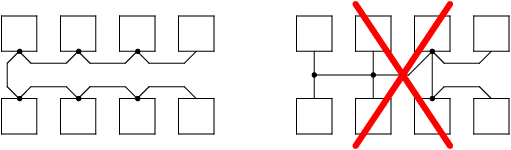
Figure 3.14, “Scheme of correct and incorrect RS-485 network topology” presents two examples of RS-485 network topologies. A properly laid network conducts in one cable from one device to the other device. Incorrectly laid network has branching of cable – such placement of network is unacceptable!
RS-485 bus requires relevant termination (impedance match
and line polarization). Termination of network should be connected only in two places
- on the ends of the network. This means these devices (network nodes) to which
cable comes and does not go further to next devices.
On Figure 3.13, “Scheme of RS-485 network connection” termination should be enabled in devices
described as LB-762 #1 (extreme device on the left side)
and LB-480(extreme device on the right side). In other
devices, located in the middle part of the network, termination
of the network must be off.
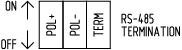
In LB-480 regulator 3 switches are used for network termination, described as
RS-485 TERMINATION (Figure 2.1, “Connectors of regulator LB-762”):
POL+ - polarization (+),
POL- - polarization (-),
TERM - impedance match.
Switches in the lower position are off, while in the top position – on.
In practice switching on termination means switching on of all 3 switches, while turning off termination means turning off of all 3 switches. The situation is theoretically possible in which switch TERM or pair POL+ and POL-, but in practice it is not present.
RS-485 interface in converter LB-480 has similar termination mechanisms
of RS-485 network. This can be done using 3 contacts which can be found on the interface plate
(available after removing the housing), described as LINE TERMINATION.
In order to turn on termination of line in converter LB-480 one should set up
all 3 contacts:
JP1 - POL+ - polarization (+),
JP2 - POL- - polarization (-),
JP3 - TERM - impedance match.
It is recommended that LB-480 converter be the terminal machine in RS-485 network (thereby that line termination be switched on in it). Of course possible is such network topology in which LB-480 converter is a device placed in the middle part of the network – in such case termination must be in other devices and this is a completely correct configuration. However, positioning LB-480 converter on the end of the network and switching on termination in it ensures correct operation of the network in the case when other equipment (regulators) may be periodically deactivated – in such case the disabled regulator does not ensure line polarization. Since LB-480 converter is a device which by principle of system operation is always on, switching on termination and polarization of line in LB-480 is the most effective way of ensuring proper RS-485 network operation. However, this requires proper network planning so that this device be placed on its end.