Table of Contents
Regulator LB-762 is used to control a single mushroom cultivation hall. It provides all necessary measurements and control over appropriate executive devices to ensure optimum climatic conditions for fungi cultivation.
LB-766 controller is used to control a single storage room. Regarding installation details, it is identical to LB-762 controller and this manual is applicable to both types.
For a greater facility, consisting of more cultivation halls, each hall must be equipped with a separate regulator. In this case it is possible to connect all the regulators into a common measurement-regulation system. In such system each regulator operates autonomously, but it is possible to control together all the regulators from one PC computer and appropriate software. Additionally, it is possible to perform some functions common for the entire system, such as measurement of external air parameters or CO2 concentration measurement.
Regulator LB-764 is LB-762 model with special modifications prepared for ”Baltic Champignons”, installation instructions also applies to this regulator.
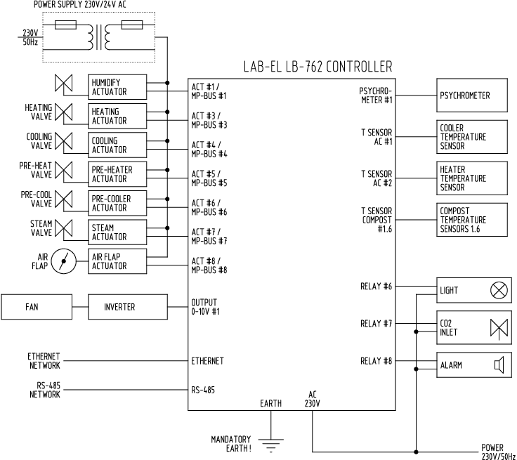
Figure 1.1, “External connections diagram of LB-762 regulator” presents a scheme of typical external connections of a single LB-762 regulator. To the regulator one should attach a set of suitable measurement probes and executive equipment so that it could perform its functions.
Psychrometers – are used for measurement of temperature and relative air humidity. The regulator may co-operate with or one two psychrometers (at least one is required for proper operation of the regulator). Attaching one psychrometer provides one-point air temperature and humidity measurement in the cultivation hall. The second psychrometer may be optionally used for temperature and humidity measurement elsewhere in the cultivation hall, for better averaging of the conditions prevailing in the room. Another function of the second psychrometer may be measurement of air parameters in air intake channel for regulation of humidity and temperature of air flowing into the hall.
Cooler temperature – single thermometer advising the regulator of cooler work.
Heater temperature – single thermometer advising the regulator of heater work.
Air supply temperature – optional single thermometer advising the regulator of temperature of air supplied to the air-conditioning tunnel (before the cooler). Application of this thermometer is optional.
Base temperature – 6 thermometers used for measurement of temperature of base in different places of the hall. It is not required to attach all 6 thermometers – the regulator correctly cooperates with any number of attached thermometers – from 1 to 6, depending on the requirements of the given installation.
CO2 concentration – for CO2 measurement, it is necessary to attach a separate dedicated CO2 concentration meter. It is possible to connect for each regulator a dedicated CO2 meter (separate meter for each hall), or use one CO2 meter for more than one hall (what permits reduction in the cost of the installation). Detailed description further the manual.
External hytherograph – to ensure better operation of mechanisms controlling climate in the cultivation hall, the regulator may use information about external air parameters flowing into the air-conditioning tunnel. This allows for using directly the properties of this air (enthalpy and humidity mass) to control climate in the hall, without use of executive devices of air-conditioning tunnel, what may reduce energy consumption. It is possible to connect to each regulator a separate hytherograph, or apply one hytherograph for the whole system (what permits reduction in the cost of the installation, as parameters of external air are normally common for all three halls and individual measurement for each hall is not reasonable). Application of this meter is optional.
Heating, cooling, moistening, initial heater valves, initial cooler, steam valves – are controlled by servomotors (some outputs are optional and may not occur in the given installation).
Ventilation – the fan is used to provide air circulation, its motor is controlled by an appropriate frequency converter (inverter). The frequency inverter is an external device, which is appropriately controlled by the regulator.
Hall lighting – the regulator has the possibility to control lighting in the hall, what is used e.g. at gasing operation.
Alarm signaling device – the regulator has the possibility to signal alarm situations (e.g. inappropriate parameters of climate in the hall, different breakdowns, etc.). The regulator has a suitable relay output for alarm signaling, which may control e.g. sound signaling device. It is possible to connect alert signalling to each regulator separately, or by a joint connection of alert outputs of all regulators in the given installation and common control with one signaling device. The application of alert signaling device is optional. It is also possible to signal an alert via control software on a PC computer.
In an installation where there is a greater number of regulators, it is possible to connect them into a data transmission network. This network ensures cooperation with a PC computer and relevant control software. By means of a data transmission network, the system can also perform additional functions:
external air parameters measurement (using single thermohygrometer),
common CO2 measurement (whe single CO2 sensor services many growing rooms).
The regulator is equipped with two data transmission network interfaces: Ethernet and RS-485. The application of a relevant network is dependent upon conditions and requirements in the given installation:
Ethernet – this network provides very high data transmission speed (10 or 100 MBit/s). Owing to great popularity of this type of networks in any other applications, it is easy to integrate it with already existing data communication systems. Limitation of the Ethernet network is distance – one cable section (between two network devices, e.g. between the regulator and switch) cannot be longer than 100 meters. This does not mean that the whole network may not have greater range – with application of proper network devices (switches, repeaters or even routers) the network can be expanded over any area. The number of devices in an Ethernet network is relatively unrestricted – the only practical limits result from the type of network devices used (switches) and the adopted IP network addressing class.
RS-485 – this network provides relatively slow data transmission as compared to the Ethernet network (19.2 kbit/s), however, its advantage is simplicity of cabling and greater scope without use of additional network devices (up to 1200 meters). As a result, cabling of networks is easier and a bit cheaper. One single RS-485 network has a limit of the number of attached devices – from 1 to 32. network extension to a greater number of devices requires application of proper network devices (repeaters).
Selection of the network type depends on the given installation – if it is possible to use Ethernet network, it is suggested to use this type of network. It provides greater comfort of use (greater transmission speed of data means smaller delay in system response, faster reading of data from regulators, etc.). If, however, the facility is very extensive and the application of Ethernet network would require use of a number of additional network devices, boosting the cost over the benefits, one can use RS-485 network.
To ensure greater reliability, it is also possible to operate both networks. In such case, the system can use the Ethernet network as the basic one, and in case of network failure (what is more likely than in RS-485 network owing to the need to apply additional network devices) it would be possible to switch to RS-485 network.
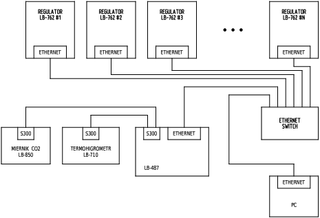
Figure 1.3, “Scheme of a system with several LB-762 regulators and Ethernet network” presents a scheme of installation in which N LB-762 type regulators are combined by means of an Ethernet network. The number of regulators that can be connected in an Ethernet network is practically unrestricted. The length of a single cable section between two network devices (in a typical case, between the regulator or computer and network switch) cannot be longer than 100 meters, but the network can be prolonged by means of relevant network devices, cascade joined switches or routers.
Comments with regard to the method of cabling Ethernet network can be found in Section 3.10, “Ethernet network”.
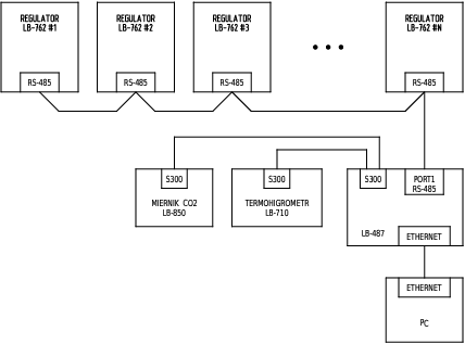
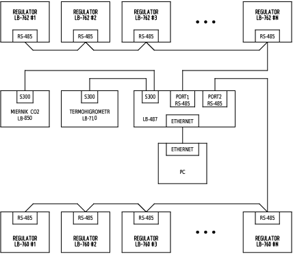
Figure 1.4, “Scheme of a system with several LB-762 regulators and RS-485 network” presents a scheme of installation in which N LB-762 type regulators are combined by means of a RS-485 network. The number of regulators that can be connected in one RS-485 network segment is from 1 to 32 (see description of RS-485 network connections), maximum total length of cable is 1200 meters.
RS-485 network requires the application of LB-480 module that works as converter of communication interfaces. Connection between a PC computer and LB-480 module is by means of Ethernet network. LB-480 module communicates with the regulators by means of RS-485 network. Additionally, to LB-480 unit common system equipment may be attached – such as an external hytherograph and CO2 concentration meter.
Comments with regard to the method of cabling RS-485 network can be found in Section 3.11, “RS-485 network”.
LB-762 regulators can be used in systems where LB-760 regulators have been used so far. It is possible to build one common system in which both types of regulators operate to provide performance of respective system functions regardless of the type of regulator (such as common measurement of external air parameters and collective CO2 concentration measurement system).
Unfortunately owing to software incompatibility between the regulators and inconsistency of communication protocols it is impossible to use a common RS-485 network for both types of regulators. LB-760 type regulators must have its own RS-485 network, while LB-762 regulators must have their own, separate network. If LB-762 regulators use Ethernet, this will necessarily be a separate network. If LB-762 regulators are connected by means of RS-485, one should route a separate RS-485 network cable for LB-762 regulators.
Figure 1.5, “Scheme of a system with LB-762 and LB-760 regulators” presents a scheme of a sample common installation with LB-762 and LB-760 type regulators, using RS-485 network for LB-762. The scheme with Ethernet network is analogous - LB-760 regulators remain connected by RS-485 network, while for LB-762 RS-485 network should be replaced with Ethernet network.
In the measuring system consisting of more regulators (both LB-762 and LB-760), it is possible to use a single hytherograph to measure external air parameters. It is also possible to connect individual hytherographs to different regulators, but with regard to the fact that they normally measure parameters of the same air, this is not reasonable. Use of a single meter permits reduction of installation costs.
Connection of external hytherograph is independent from the type of applied
data transmission network (Ethernet/RS-485).
On Figure 1.3, “Scheme of a system with several LB-762 regulators and Ethernet network” i Figure 1.4, “Scheme of a system with several LB-762 regulators and RS-485 network”
external hytherograph is described as LB-710 HYTHEROGRAPH.
Hytherograph can be attached to any device in the network that has an S300 input. This may be LB-480 module (having 8 S300 inputs), as well as each of LB-762 regulators, having 2 S300 inputs (despite connection to individual regulator, the whole system can be configured to use this hytherograph as a source of data for all other regulators). However, for reasons of reliability of the system, it is advised to connect hytherograph to LB-480 unit – this module is common for the entire system and operates independently of all regulators. In the case of connecting the hytherograph to LB-762 regulator when the regulator is disabled or fails for some reason, the whole system of collective measurement of external air parameters will cease to operate.
![[Important]](images/important.png) |
Important |
|---|---|
For operation of collective measurement of external air parameters it is necessary to ensure ongoing operation of the control software on a PC computer. |
In the measuring system consisting of more regulators (both LB-762 and LB-760), it is possible to ensure CO2 concentration measurement in two ways:
local measurement – each regulator has its own individual CO2 meter,
collective measurement – one CO2 meter covers more cultivation halls.
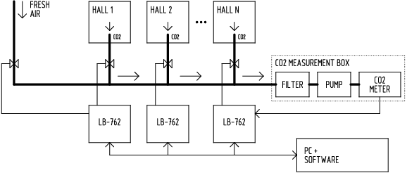
Connecting individual CO2 meters is relatively costly, the application of collective measurement permits reduction in installation costs. Figure 1.6, “Scheme of a collective system of CO2 concentration measurement” presents the scheme of a typical installation of collective CO2 measurement. The system consists of the following elements:
CO2 meter – used for CO2 concentration measurement in the air supplied from different halls,
pump – provides air suction from different halls,
valves – provide opening of air supply from different halls.
The whole operates as follows: the system opens valves in cycles for different halls, accepting at a given moment air only from one hall. The pump sucks in air for a given time and delivers it to the meter of CO2 concentration (the suction time is dependent on the length of pipes supplying air). After the specified time has elapsed, one may consider that air which has arrived to the meter corresponds to that in the hall and the CO2 meter makes the final measurement whose result is sent to the regulator controlling the relevant hall. Then, the air supply valve for the particular hall is shut down, and opened is the valve for the next hall. The whole continues in cycles.
Additionally, it is possible to incorporate to the system CO2 concentration measurement for external air. This has two functions: periodic "blowing" Of the CO2 meter with fresh air with low CO2 concentration and verification of correct measurement by means of fresh air. As CO2 concentration in cultivation halls is usually much higher than outdoors, the meter working all the time in the conditions of high concentrations of CO2 shows a tendency to overestimate the results, what can be prevented by periodic delivery of fresh air. This also permits verification of correct measurement – CO2 concentration value in external air is usually a predictable value of a few hundred ppm. A radically different result means incorrect operation of the meter or of the entire system of collective CO2 measurement.
The limitation in the quantity of halls taking part in the collective CO2 measurement is duration of the measuring cycle. For instance: at the time of air suction from the hall of 5 minutes and 5 cultivation halls plus external air measurement, we have cycle time = 5 minutes * (5 + 1) = 30 minutes. This means updating of CO2 result in each hall every 30 minutes. Increasing the number of halls prolongs this time in two ways: once, that each additional hall should be considered in the cycle, two, that the length increases of pipes supplying air to the meter and, at the same time, it may be necessary to prolong the measurement time from one hall. Too rare updates of CO2 concentration measurement result does not let LB-762 regulator effective regulate fresh air supply to the hall and, at the same time, does not permit effective CO2 level regulation.
In a greater system where the number of halls and regulators would cause too long CO2 measurement cycle time, it is possible to divide the collective CO2 measurement system into smaller parts. In such case in the system a greater number is installed of CO2 meters, each of which covers some selected group of halls. One should create several such groups, depending on size of the system. In such case each collective CO2 measurement group operates on its own and independently of the others. For each group it is advised to attach CO2 concentration measurement in external air, for reasons previously discussed. Separate groups of collective CO2 measurement operate independently, but within one network of data transmission – it is not required here to split the entire system into separate data transmission networks, in accordance with breakdown of CO2 measurement. The data transmission network is common, CO2 measurement groups are independent of this.
|
Important |
|---|---|
For operation of collective CO2 concentration measurement, it is necessary to ensure ongoing operation of the control software on a PC computer. |