Table of Contents
![[Warning]](images/warning.png) |
Warning |
|---|---|
For the purpose of preserving user safety, all operations on connections should be conducted with regulator power supply switched off! |
To obtain access to connections it is necessary to open the regulator casing. For this purpose:
unscrew four plastic screws on the front panel,
open the Casing lifting up the front panel on hinges.
Connections are placed in the rear part of the casing, mostly along side edges. The exception are: Ethernet link placed on the top and power supply and earthing link placed on the bottom.
All connections use plugs to which wires are fixed by means of screw clamps or spring clamps.
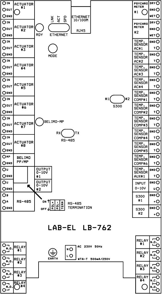
The distribution of connectors is presented on Figure 2.1, “Connectors of regulator LB-762”. Description of functions of different connectors is included below in the manual.
On main plate of the regulator (in the rear part of the casing) there are several light diodes, which are supposed to signal regulator status. The function of these diodes is above all to provide a diagnostic tool – they are important mostly at the time of installation and start-up, later while normal operation access to them is not required. All signaling elements important during daily operation are located on the front panel of the regulator casing.
The following LEDs are available:
regulator readiness to work
Ethernet connection (LED out - no connection, LED on - connection active)
data transmission through Ethernet interface (each LED flash is associated with data receipt or transfer)
data transmission speed through Ethernet interface (LED out – 10 MBit/s, LED on - 100 MBit/s)
data transmission through interface of servomotors BELIMO MP (each LED flash is associated with data receipt or transfer)
receipt of data through RS-485 interface
sending of data through RS-485 interface
data transmission through interface S300 no. 1 (each LED flash is associated with data receipt)
data transmission through interface S300 no. 2 (each LED flash is associated with data receipt)
Errors in operation of the regulator are signalled both on the display on the the front panel as well as by means of signaling diodes on the main plate of the regulator (possible is e.g. regulator failure condition which does not permit display of the relevant announcement on the displays, in such case the only possible signaling is by means of diodes on the plate).
Errors are announced as follows:
On the main display located on the front panel
the message is displayed SOS XXXX, where XXXX may have
different numeric values, denoting the error code.
ALARM diode and buzzer (sound signaling) broadcast SOS message in the Morse alphabet.
The following LEDs are used to signal failure: RDY, ETHERNET LNK, ETHERNET ACT and ETHERNET SPD. LEDs flash in cycles broadcasting SOS message in the Morse code, similarly to the signalling on the front panel. The error code is characterized by a combination of diodes which flash and which remain off.